
Engine Library / Steam engines
Horizontal Slide-Valve Stationary Steam Engine.
A fixed horizontal cylinder, a guided piston rod and a flywheel turn steam pressure into steady rotary motion.
This was a versatile family of workshop and mill engines, built in many sizes and layouts through the nineteenth century. The D-slide valve and its eccentric make the steam cycle visible as well as the mechanical motion.
At a Glance
- Type
- Reciprocating stationary steam engine
- Layout
- Single horizontal cylinder; often double acting
- Steam control
- Slide valve driven from the crankshaft
- Main output
- Rotating crankshaft and flywheel
- Historical use
- Mills, workshops, pumps and generators
- Status
- Preserved, demonstrated and modelled today
Engine name and overview
A horizontal engine made for fixed work.
A stationary engine stays in one place and drives machinery through a shaft, belt or direct coupling. Here the cylinder lies horizontally on a bed, and the piston travels back and forth along the engine’s length. A slide valve routes steam to opposite ends of the cylinder while the crank and flywheel turn.
Historical background
Many builders, many sizes.
Horizontal stationary engines became common in nineteenth-century industry. They were built by many firms rather than invented as one standard machine. Surviving records range from an 1859 Ransomes and Sims sales model to the full-size 1864 Durn Mill engine and an 1890 Dugdill workshop engine. Their differing beds, guides, accessories and power ratings show how broad the type became.
Why it was developed
Practical power for a working site.
Factories and workshops needed rotary power for line shafts, pumps and, later, electric generators. A horizontal bed could place the cylinder, guide and crank in a clear line at floor level, with substantial bearings supporting the shaft. Builders varied the size and fittings to match the duty, available steam and installation.
Where it was used
From mills to small shops.
Documented examples include the 250 hp Durn Mill condensing engine and John Dugdill & Co’s 3 hp shop-lighting dynamo engine. Other horizontal engines powered workshop machinery and pumping plant. These two ratings illustrate diversity; they are not a typical power range for every slide-valve engine.
How it works / power train
Follow the motion from steam to flywheel.
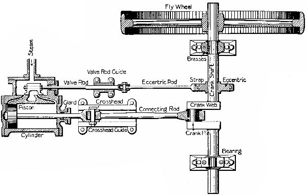
Steam pressure pushes a piston inside the fixed cylinder. The piston rod carries that straight-line motion to a crosshead, which slides in guides. The crosshead keeps the rod aligned while the angled connecting rod pushes a crank. The crank rotates the crankshaft, and the attached flywheel carries momentum between power strokes and through dead centres. The flywheel stores energy; it does not create it or guarantee that an engine stopped exactly on dead centre will start itself.
How it works / valve gear
How steam changes sides.
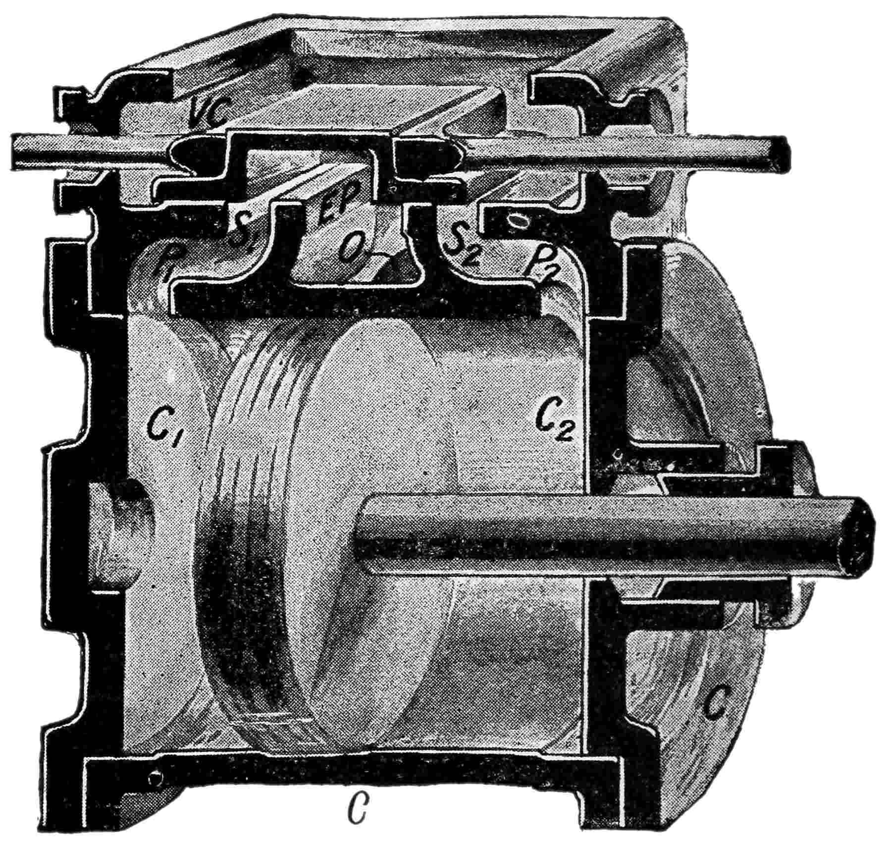
The D-slide valve moves across a flat port face inside the steam chest beside the cylinder. In the common outside-admission arrangement, live steam fills the chest around the valve. As one cylinder port opens to live steam, the valve’s hollow underside connects the opposite port to the central exhaust passage. On the return stroke the valve exchanges those roles, giving alternating admission and exhaust at the two ends.
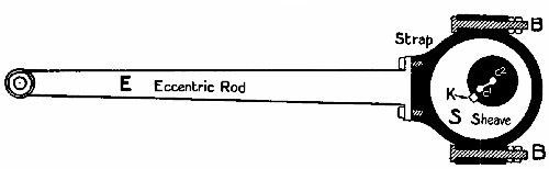
An eccentric is a circular sheave mounted off centre on the crankshaft. It turns inside an eccentric strap; the strap and eccentric rod move the valve rod back and forth. The strap is the ring around the sheave, while the rod transmits its motion. Valve lap, lead and eccentric setting affect the exact admission, cutoff, release and compression events, so no single timing angle applies to every engine.
Key mechanical features
Parts that make the layout readable.
- Bed and bearings: keep the cylinder, crosshead guides and crankshaft aligned.
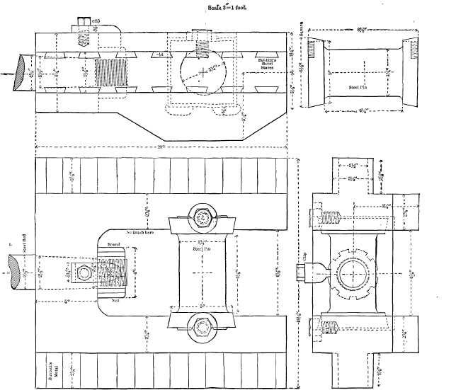
- Crosshead and guides: take the side load from the connecting rod away from the piston rod.
- Crank and flywheel: convert reciprocation to rotation and smooth the varying turning effort.
- Steam chest, D-slide valve and ports: direct admission and exhaust without moving the cylinder.
- Eccentric, strap and valve rod: synchronize valve movement with crankshaft rotation.
Typical specifications
No single standard size.
The defining features are the horizontal cylinder, reciprocating piston and crank drive, not a fixed bore, stroke, speed or output. Published examples span small workshop engines and large mill engines. Output, steam pressure, speed and whether the engine condensed its exhaust depended on the installation. The 3 hp Dugdill and 250 hp Durn Mill records are examples, not a recommended specification range.
Advantages and limitations
Clear, robust, but site dependent.
The layout offered accessible rods, bearings and valve gear for inspection and maintenance, while a large flywheel helped smooth torque. It required a steam supply, lubrication, regular attention and room for the long motion train and driven machinery. A plain slide valve also involved sliding friction and timing compromises; later valve systems could manage steam admission more precisely.
Why it became less common
Power systems changed.
Factories gradually moved away from individual reciprocating steam engines as central electric supply and electric motors became practical. Electric drives could put power closer to each machine without a boiler, steam piping and mechanical line shafts. This was a gradual shift that varied by industry and place; surviving steam plants continued working for many years.
Modern use and surviving examples
Preserved as working history.
Museums preserve horizontal engines and scale sales models that show their mechanisms. The Ransomes and Sims model documents a D-slide valve and crankshaft eccentric; the George Bower workshop engine documents an open T-slotted crosshead guide and D-type valve. Restored finishes and replacement parts should be read as part of an object’s later history, not automatic evidence of its original appearance.
Notable variants and related engines
One layout, several working arrangements.
Horizontal engines could be non-condensing or condensing; they could have open bar or T-slotted crosshead guides, and some added governors or pumps. More elaborate valve gear, separate cutoff valves and reversing arrangements served different duties. Those variations should not be confused with the plain, non-reversing D-slide arrangement explained here. For a simpler related steam mechanism, see Wolfgang Engineering’s Single Cylinder Wobbler, whose cylinder oscillates instead of remaining fixed.
Image gallery
What the drawings show.
The four period drawings on this page serve different purposes: Williams’s plan traces the whole engine, Tennant’s section reveals the steam path, and the crosshead and eccentric details isolate two easily confused mechanisms. All are technical illustrations, not photographs of one specific surviving engine.
Image credits appear with each drawing. Project Gutenberg lists each source book as public domain in the United States; that is the commercial-use basis for their use on this U.S. website.
Sources and further reading
Explore the original records.
- Museums Victoria, Ransomes and Sims sales model (1859) — documented horizontal D-slide engine and eccentric.
- Powerhouse, George Bower workshop engine — documented guide, valve, bed and bearings; catalogue measurements are inconsistent, so none are used here.
- Science Museum Group, Durn Mill engine and John Dugdill & Co engine — contrasting mill and workshop examples.
- Archibald Williams, How It Works; W. J. Tennant and J. H. Kinealy, The Slide Valve, Simply Explained; Joshua Rose, Mechanical Drawing Self-Taught — period mechanism explanations and drawings.
- Industrial Press, Steam Engines (1911) — motion and valve-event background.
- Historic American Engineering Record, Continental Gin Company — documents the gradual shift from steam-driven line shafts to electric group and unit drives.