
Engine Library / Gasoline / Piston
Chevrolet Small-Block V8
Follow the pushrods from the camshaft to the overhead valves.

Early Chevrolet small-block V8 on display, photographed in 2011.
JOHN LLOYD (Hugo-90) — Very First Chevrolet Small Block Built (6326258301).jpg. Source · CC BY 2.0 Generic · Original. Unmodified; resized for display.
.jpg)
At a Glance
- Layout
- Liquid-cooled 90-degree V8
- Cycle
- Four-stroke gasoline, spark ignition
- Valve drive
- Cam in block → lifter → pushrod → rocker → valve
- Introduction
- 1955 model year
- First displacement
- 265 cu in / about 4.34 L
- Scope
- Traditional Gen I; later generations distinguished
Overview
The traditional Chevrolet small-block puts the valves above the pistons but keeps the camshaft down inside the block. Pushrods bridge the distance. That relationship is the starting point for understanding a family associated with ordinary road cars, performance cars and custom builds.
Introduced for 1955 at 265 cubic inches, the engine developed into many displacements and configurations. This article concentrates on Generation I. GM's later LS and modern LT engines belong to a wider small-block lineage, but the shared name does not make their parts or details identical. [S1, S3]
Historical Background
Chevrolet appointed Ed Cole chief engineer in 1952 with a brief that included a light, economical V8. He led an engineering team; attributing the whole engine to a lone inventor would obscure that work. [S1]
The V8 joined the Corvette range in 1955. Museum records connect this period with Zora Arkus-Duntov's efforts to interest Chevrolet in younger performance buyers and competition. Subsequent 283, 327 and 350 versions expanded the engine's reach while retaining the basic cam-in-block overhead-valve arrangement. [S2, S3]
Why It Was Developed
A volume-production manufacturer needed an engine that fitted the car and the production budget. Chevrolet's new V8 had to improve performance while remaining economical to build. A compact package offered room for use across ordinary vehicles as well as more specialized versions. [S1]
Its later adoption by custom builders followed from a different advantage: an established engine came with accumulated parts, knowledge and development. That subsequent popularity should not be mistaken for the sole original design objective. [S4]
Where It Was Used
Chevrolet cars and trucks, Corvettes and Camaros supplied familiar production applications. Custom and competition vehicles gave the traditional family a wider life. [S3, S4]
The National Corvette Museum's 2022 “Corvette Powered” exhibition included vehicles such as the Scarab, Bizzarrini Strada and Avanti II. They demonstrate Chevrolet power beyond Corvette, with individual installations requiring their own identification. The exhibition archive does not promise that these vehicles remain on display. [S11]
How It Works
Combustion and valve motion are separate chains working in time. In each cylinder, intake brings in a charge, compression prepares it for ignition, combustion supplies the power stroke, and exhaust removes burned gas. The piston applies force through its connecting rod to an offset crankpin, rotating the crankshaft. Eight cylinders contribute in succession over the four-stroke cycle's two shaft revolutions. Actual ignition and valve events overlap the idealized stroke boundaries. [S5]
The camshaft turns at half crankshaft speed. A cam lobe lifts a lifter, which raises a pushrod. The pushrod turns a rocker arm on its pivot; the rocker's opposite end opens the valve. A spring closes it as the cam's lift falls away. Thus a low-mounted cam can operate valves in the cylinder heads. [S6]
Early small-blocks used individual stamped-steel rockers mounted on studs. Later and aftermarket systems differ. The accompanying diagram explains the generic overhead-valve chain; it is not a drawing of a specific Chevrolet engine. [S7]

Generic overhead-valve mechanism: cam → lifter → pushrod → rocker → valve. This is a schematic, not a Chevrolet-specific cutaway.
Ian Brockhoff / IJB TA at English Wikipedia — Pushrod2.PNG. Source · CC BY-SA 3.0 Unported · Original. Unmodified; resized for display.


Key Mechanical Features
- Two banks of four: the 90-degree arrangement groups eight cylinders around one crankshaft. [S8]
- Five main-bearing locations: supports along the shaft carry its loads in the early design. [S8]
- Heads with operating valves: this differs from a flathead's valves beside the bores and from an overhead-cam engine's cam location.
- Individual rocker mechanism: the original arrangement simplified the hardware above the heads; performance systems later used different support arrangements. [S7]
- Changing induction and equipment: carburettors, mechanical injection and electronic injection identify different versions. Replacement-engine documentation also warns of compatibility differences. [S3, S9]

Chevrolet small-block display engine, with the carburetor and rear-mounted distributor visible.
Daderot — Chevrolet small-block engine - Automobile Driving Museum - El Segundo, CA - DSC01736.jpg. Source · CC0 1.0 Universal Public Domain Dedication. Unmodified; resized for display.

Typical Specifications
This example is the standard 1955 passenger-car 265, not a Corvette option or a later 350. [S8, S10]
| Item | Representative 1955 265 |
|---|---|
| Configuration | 90-degree pushrod V8 |
| Displacement | 265 cu in / about 4.34 L |
| Bore × stroke | 3.75 × 3.00 in |
| Compression ratio | 8.0:1 |
| Advertised output | 162 gross hp at 4,400 rpm |
| Fuel and cooling | Gasoline; liquid cooling |
Chevrolet's period brochure also lists a 180-hp option. The table's historical gross horsepower uses different test conditions from a modern net rating. Neither a performance option nor a present crate engine should inherit this table merely because it is called a small-block. [S8, S10]
Advantages and Limitations
Compact packaging and extensive parts support helped builders adapt the engine to many jobs. Its exposed pushrods and rockers also provide a useful way to study the connection between cam motion and gas flow. [S4, S9]
The intervening valve-train parts have mass and flexibility. Higher speed, lift and spring loads make control more demanding; performance rocker developments address those demands. That explains a design tradeoff without suggesting every standard engine was unreliable. Variety is another practical limit: a famous family name cannot guarantee a head, intake, flywheel or accessory will fit a different version. [S7, S9]
Why It Was Replaced or Discontinued
The small-block lineage changed rather than ending on a single date. Gen II LT1 arrived in the Corvette for 1992 with revised cooling. Gen III LS1 followed for 1997 with major changes to the architecture, heads and ignition. Both require treatment as identified developments. [S3, S12]
Traditional engines continued in replacement and enthusiast channels as newer architectures entered production vehicles. “Still available” therefore does not mean a current car uses an unchanged 1955 design. [S4]
Modern Use and Surviving Examples
Chevrolet's June 2026 account discusses traditional small-block crate offerings alongside separate LS, LT and big-block lines. This dated manufacturer evidence supports continued supply in that context. [S4]
Preserved road and competition cars show different stages of the family, while modified engines reveal the work of later builders. The photographed Kritzeck Motorsports 327 is identified by its source; its visible equipment and finish do not establish a standard factory configuration. Museum collections and former exhibitions should be checked separately for current display arrangements. [S11, S12]
Notable Variants and Related Engines
- 265, 283 and 327: early and expanded Gen I displacements. [S3]
- 350: introduced in 1967 and widely associated with the traditional family. [S3]
- 400: a larger traditional displacement. [S3]
- Gen I LT-1: a performance designation associated with the 1970 period. [S3]
- Gen II LT1: a distinct 1990s development with reverse-flow cooling. [S3]
- LS and modern LT: later architectures, requiring their own specifications. [S3]
Include generation and period when using LT1/LT-1. The Ford Flathead V8 provides a useful comparison of valve placement; neither engine's mechanism should be explained using the other's arrangement.
Image Gallery
The views distinguish an early display engine, a generic valve schematic, another preserved small-block, a 1955 car and a later 327 installation. The car photograph supplies period context, not proof of the engine fitted to that particular vehicle. Photograph titles alone do not authenticate “the first” engine or factory originality.
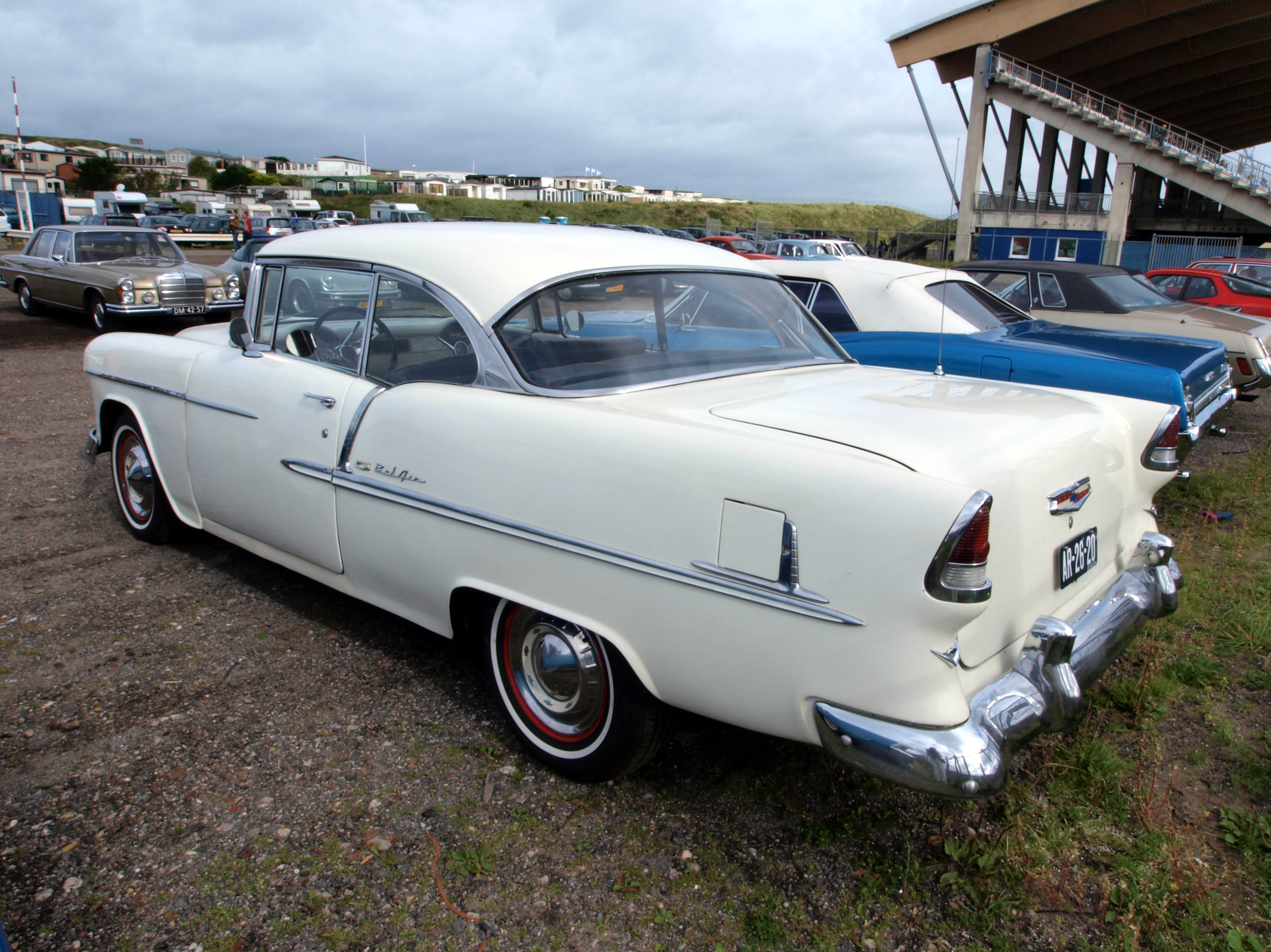
1955 Chevrolet Bel Air two-door hardtop, photographed at Zandvoort in 2011.
Alf van Beem — 1955 Chevrolet Bel-Air 2dr Hardtop.JPG. Source · CC0 1.0 Universal Public Domain Dedication. Unmodified; resized for display.


Kritzeck Motorsports Chevrolet 327, photographed from above in 2024.
MotorsportsMadness — Kritzeck Motorsports 327 Top 2.jpg. Source · CC BY 4.0 International. Unmodified; resized for display.

Sources and Further Reading
Museum histories and Chevrolet's timeline establish the development context. The period report and brochure define the table's 1955 example; mechanism and replacement-engine sources explain the valve train and compatibility limits. Dora's source register records access on 2 October 2026. No tuning or installation instructions are supplied here.
- S1. National Corvette Museum: Ed Cole
- S2. National Corvette Museum: The Turning Point
- S3. Chevrolet Performance: Small-Block Family History
- S4. Chevrolet: From Small Block roots to modern crate power, 11 June 2026
- S5. NASA Glenn: Internal Combustion Engine Stages
- S6. FAA: Powerplant Handbook AC 65-12A
- S7. Jesel Valvetrain: Shaft Rocker Story
- S8. Racer Brown, January 1955 technical report, republished by HOT ROD
- S9. Chevrolet Performance: 350 HO specification/instruction document, revision 23 September 2020
- S10. Chevrolet Motor Division: 1955 brochure, archived scan
- S11. National Corvette Museum: Corvette Powered exhibition archive
- S12. National Corvette Museum: collection records